How to Build a Computerized Android Robot Head
for $600.00.
Version 2, 02/11/2006
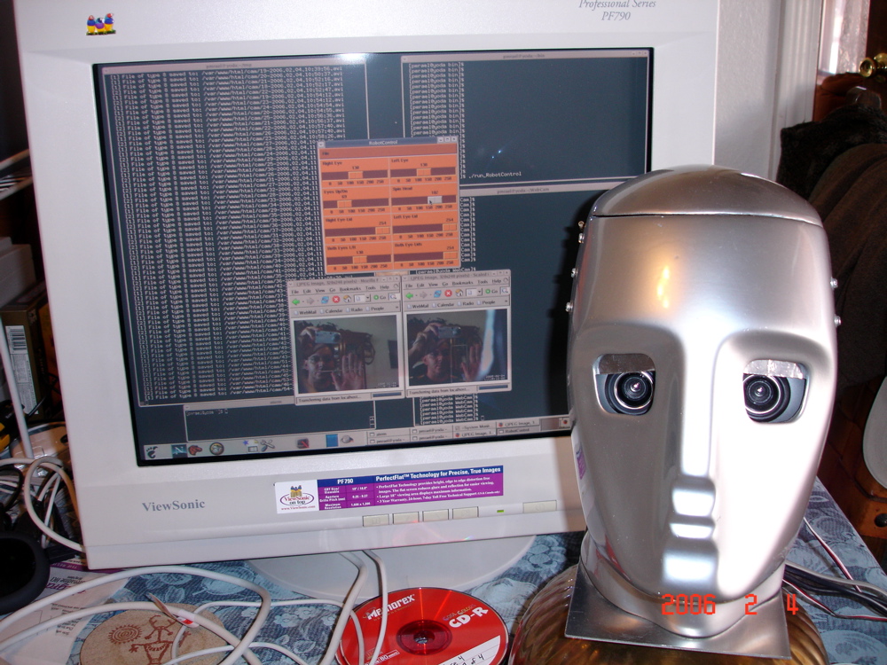
Figure 1. Robot Maxamilian (R. Max). Dual eye cam image streams
being processed in two windows in computer. Processing software is
"Motion" (Open Source) + pwc web cam kernel module. Servos are being
controlled by "RobotControl" perl/tk (app elsewhere on this web site).
<\p>
Except for the head, all components for the android head are found in hardware stores, computer stores, RC-Model car/airplane stores, and hobby shops. Table 1 shows the items required to build R. Max, and approximate cost. The hobbyist supplies a drill, hack-saw, metal file, vise-grips, flat-head and phillips-style screw drivers, sheet-metal cutters, wrenches, and a Dremel-like cutting tool.
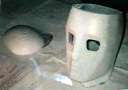
The head is the most difficult part to find. This head (Figure 2) was found at a mannequin services shop. It is made of fiberglass. This means all cutting, drilling and filing must be accompanied by a breathing filter. This safety issue is the primary drawback to using an unprepared fiberglass head. An alternative is to use [still no list of alternate heads :-(]
Figure 2: Primered R. Max with access door disconnected.
Some things to consider when choosing a head are that the space behind
the eye openings has enough room for the moving Eye-Bracket. The width
of head must accommodate both eye-cams mounted on a bracket. Also of consideration
is to ensure the eye bracket can be removed with the rest of the Cranium
Chassis.
The eyes can be cut out with a Dremel tool. Rounded-corner square eyes
seem to have a mechanical look that is aesthetically pleasing for this
head. The top of the head can be cut open with a hack-saw, but a band-saw
would probably make the straightest cut. If the forehead is tall, the cut
can be made high enough to not interfere with the smooth forehead.
The removable Cranium Chassis (Figure 3, 5) is designed to contain
most of the functionality of the internal workings of the head. The Cranium
Chassis is functionally decoupled from the case of the head except for
the eye-lid guide tracks and the eye-bracket mounting studs. This modular
design allows either the Cranium Chassis or the head case to be modified
without impacting the other. The Chassis can be removed and placed inside
a different head case.
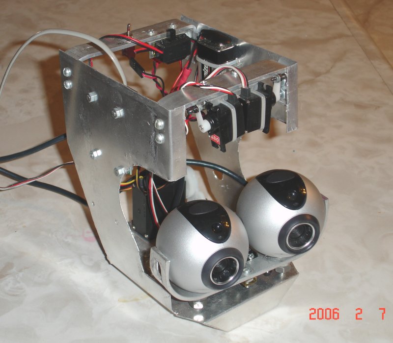
Figure 3 - Cranium Chassis.
The Cranium Chassis rests on a piece of iron strap spanning left-right across the neck. The strap is inserted into thin slits cut into the fiberglass (Figure 4). Goop was applied to make that permanent. The Chassis box can be prototyped with thin cardboard. A large, square-cornered box won't fit into the head because the rear corners hit the back of the head, so the rear corners are removed. This leaves the box in Figure 5. With corners cut out, a larger box will fit in the head than would seem likely.
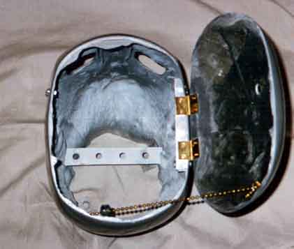
Figure 4 - Inside of head without Cranium Chassis.
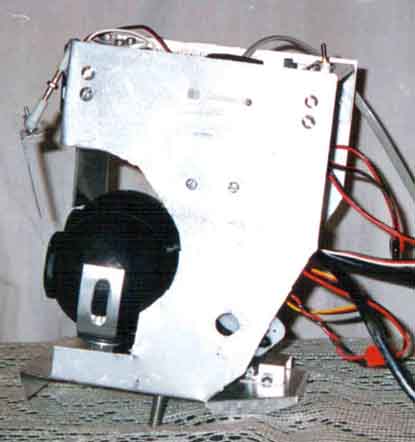
Figure 5 - Cranium Chassis, side view.
Two holes are drilled in the base of the Chassis to match the holes
in the iron strap underneath. It is fastened with the bolts pointing down.
The top of the box is kept open but rigid with two straps of 1/8" X ½"
X 6" aluminum. These two front and rear straps are used also as handles
to remove the Chassis. It's useful to have as much open space as possible
to tinker with and check the components.
The Eye Bracket is the mounting point for both eye-cams. It's a
1/8" X 3/4" X 7" aluminum bar that looks like a wide letter 'U' (Figure
3, 7). The bar can be manually bent on a vise using several small bends
to achieve two large round bends. Each eye-cam is bolted to the bracket
in such a way as to allow free rotation. An oversized bolt inserted through
the eye bracket is tightened into the eye-cam. Two nuts are tightened against
each-other at the precise point as to maintain a minuscule gap. This allows
the eye-cam to rotate freely.
On both ends of the U are holes (Figure 5) which attach to mounting studs on the inner wall of the head. The holes are drilled at points which run through the centers of both eye-cams. The holes are elongated vertically to allow the eye-bracket to slide onto the studs from above.
When attached to these mounting studs the eye bracket spins. This provides for up/down eye motion. The mounting studs are bicycle-hub thread-protectors inserted through the hole of iron-strap (Figure 9). The strap is bolted to the inside of the head. A small washer takes up slack.
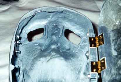
Figure 9 - Eye-lid guide tracks and the Eye-Bracket mounting studs.
Behind each eye-cam and attached indirectly to the Eye-Bracket are two sub-micro servos (Figures 6,7). The servos each attach to the backs of the eye-cams via a tie-rod to ball-joints. The ball-joints are glued to the eye-cams with goop. The servos are attached to a copper bracket which is connected to the eye bracket.
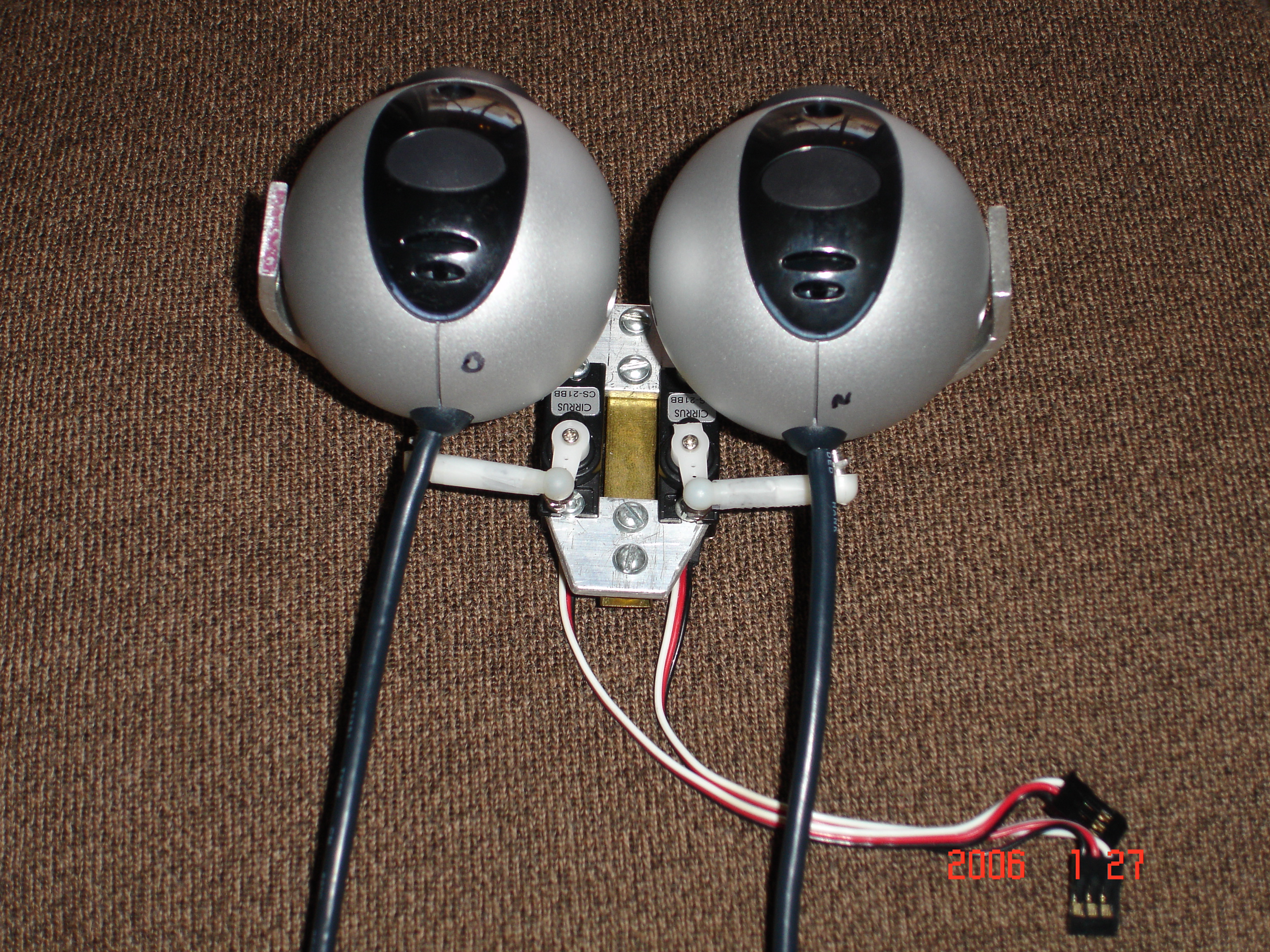
Figure 6 - Eye-Cams and servos, rear view.
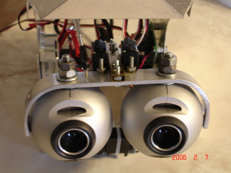
Figure 7 - Underside of Eye Bracket.
A ball-joint is mounted on the left-underside of the eye bracket. This connects through a tie-rod to a servo mounted on the bottom of the Cranium-Chassis (Figure 8). This servo controls up/down eye-cam motion.
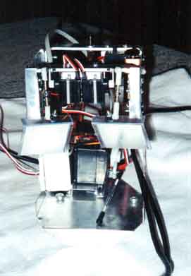
Figure 8 - Cranium Chassis with no eyes.
The servo on the bottom controls eye up/down
motion. The tie-rod connects to the Eye
Bracket.
The eye cameras are Logitech QuickCamPro-4000 The eye cams have USB port. The software that came with these cameras does not allow the programmer to get into the internals of the images in real time, so Open Source software called "Motion" is used instead in combination with the "pwc" kernel module device driver. ("pwc" is short for Philips Web Cam).
The old Eye Cams had green plastic rings attached to the front, but
the new cams are left original on the front. The old eye cams had a nut
inside the cam into which a bolt was screwed into. The QCP-4000 cams
have a plastic hole with a spring clasper. This entire clasper can be
removed (VOID THE WARRANTY) and a bolt head and washer can be placed inside the cam
with the threads protruding out/down of the cam onto which the nuts are
attached to.
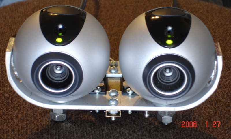
Figure 9.1. Close-up of the Eye cams and bracket.
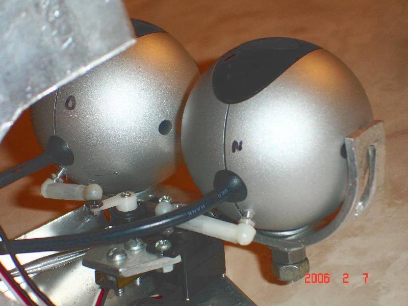
Figure 9.2. Back side of eye cams showing ball joints. The ball joints are screwed into holes drilled directly into the eye cams. First, the eye cams were disassembled to ensure the drilled hole would not damage any internal components. THIS WILL VOID THE WARRANTY! To dissassemble the cams there is 1 screw in the side hole, plus a flat edge to pry apart the two halves. Careful to not fully pull both sides apart: I didn't, you're on your own if you do.
The eye-lids are constructed of the thick plastic wrapping that
accompanies common goods enclosed in plastic (Figures 3,5). The eye-lid
plastic has to be able to take a 90 degree bend and maintain it. A ball-joint
is mounted on top. From that ball-joint, through a tie-rod, is another
ball-joint connected to a sub-micro servo. These two servos are attached
with plastic tie-wrap onto the front Chassis handle. Aluminum tape is taped
onto the front of the plastic eye-lids for a shiny appearance.
Two parallel guide-tracks made of the same plastic are attached on both
sides of the interior of the eye-openings (Figure 9). The guide-tracks
are mounted with goop. The outer track is half the length of the other
because as the eye-cam sweeps outward the tolerance doesn't allow for a
track to be present.
The servo controller is a Scott Edwards Electronics Mini-SSC-II
servo controller (Figure 10) . It is the interface between the computer
and the servos. The controller connects to a computers serial port. The
controllers phone-style, modular jack connects to a computer's serial port
via a DB-9 pin to modular converter. The handshaking is 8N1; 8 data bits,
no parity, 1 stop bit. Figure 11 shows a schematic of all the electrical
components. The Mini-SSC-II is bolted to the right side of the Cranium
Chassis.
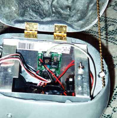
Figure10.1 - Mini-SSC-II servo controller mounted in Chassis.
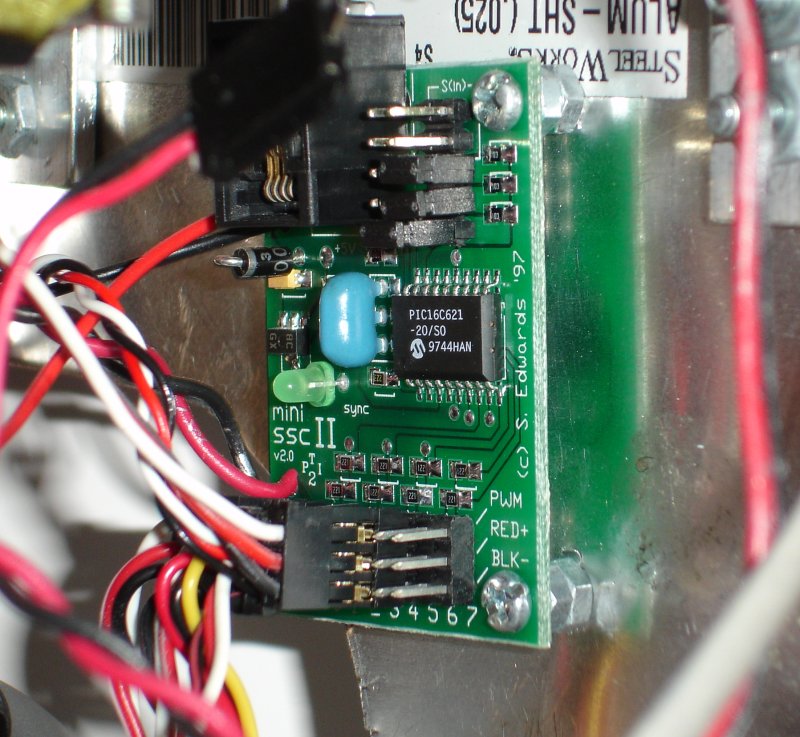
Figure10.2 - Close-up of the Mini-SSC II.
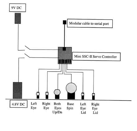
Figure 11 - Schematic.
The Mini-SSC-II has eight connectors for servos, six of which are used
in R. Max. Two controllers can be connected together to drive 16 servos.
There is a scalability option to chain 32 controllers to drive 255 servos
via special ordering options from the company. The baud rate for the SSC
is jumpered to 9600. The rotation range is jumpered to a maximum of 180
degrees. More range means less precise steps.
The communications protocol is 3-byte data packets. The first byte is
#255 for ATTENTION. The second byte is for servo number 1-16 or more. The
third byte is for servo rotation position in the range of 0-254. This protocol
is simple and easy to program.
Two DC power sources are needed: one for the Mini-SSC-II and another
for the servos. The Mini-SSC-II requires a 9-volt source, so a 9-volt battery
is attached on the left side of the chassis (Figure 3). An on/off toggle
switch is mounted inline at the top of the rear Chassis handle. The servos
require a separate 4.8-6V power source. It connects into the Mini-SSC and
is fed indirectly to the servos. This battery is mounted below the SSC
(Figure 8) with a plastic tie-strap, and it also routes power through a
Model RC on/off toggle switch. Optionally, a power supply (Jameco part
#116089) eliminates battery recharging. The eye-cams get their power from
the computer.
The Access Door is made by sawing open the top of the head. The
door is connected to the head with two small hinges (Figure 4). There was
no place on the door to bolt the hinges into, so a foundation of PC-7 Epoxy
was made. The hinge is bolted directly into the PC-7.
A frame of aluminum channel was made to connect the door to the head.
This frame is attached to the head with two bolts which can be seen on
the outside of R. Max's right side. The frame was filed to match the round
curvature of the side of the head. A stopper chain connects from the door
to the back of the head to hold the door open.
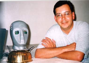
The spinning base consists of an inverted brass plant-holder (Figure
18). Inside is a vertically-mounted front bicycle wheel hub. A 1" hole
is cut in the center of the brass through which the bicycle hub bolt protrudes.
The top hub flange is bolted directly into the brass (Figure 12). The thick
aluminum plate is bolted to the protruding hub bolt. It is on this plate
that the head rests.
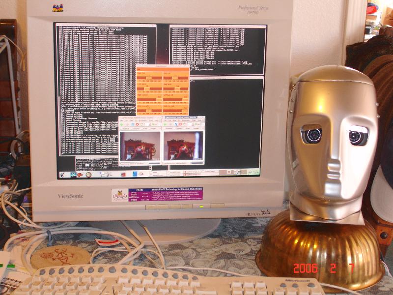
Figure 18 - R. Max android robot head and computer. Notice each web cam
image in a browser window, via "Motion" Open Source software. Also the
RobotControl Perl/Tk app to control the servos is above the eye cam images.
A sail servo is attached directly to the lower hub flange. This servo's rotor is attached to the lower threaded hub bolt via ball joints and a tie rod. As the servo motor turns, it turns the hub bolt which turns the head.
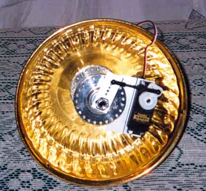
Figure 12 - Underside of base showing bicycle hub and servo.
The eye-cams are powered from the computer so they can be on anytime
the computer is running. They run independent of the Mini-SSC-II. The controller
On-button is a shiny metal switch (Figure 10). The servo On-button is somewhat
less visible next to the other switch. The servos should be powered on
first. When the Mini-SSC-II is powered on it positions all servos to the
middle.
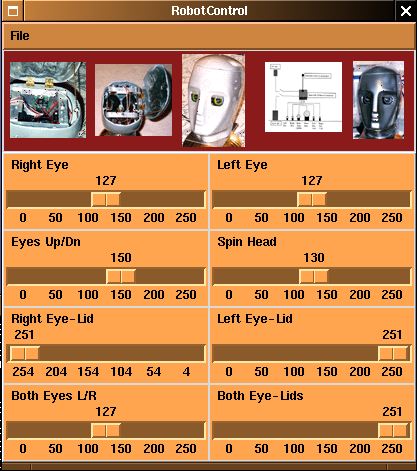
Figure 13.
- A non-fiberglass head is preferable, like aluminum, or clear-plastic
to see the internals moving.
- The face drops back on the sides too fast, resulting in the eyes being placed far back (Figure 16).
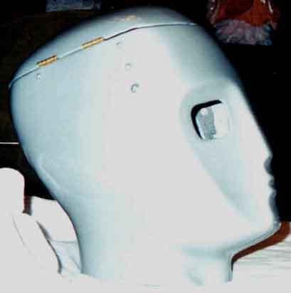
Figure 16 - Side profile of R. Max. Note the receding side of face.
- I'd like the face to be both hinged and replaceable.
- The base servo sometimes bounces on it's servo-saver spring, so a Model-RC car shock absorber will have to be added.
- The chrome-color spray paint looked great (Figure 17) but retained
finger prints. The protective gloss turned the shiny color grey. UPDATE
4-8-99 - A Water-based clear-coat doesn't grey-out the shine!
This is solved. An example of such a clear-coat is Krylon Living
Color Clear-Gloss Latex Enamel, Low Odor.
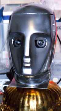
Figure 17 - Chrome look and feel. This is my favorite photo. -Pat
- Software-controlled eye-cam focus is needed.
- Speech recognition software is in the early-evaluation stage.
- The fastener bolts for the head onto the aluminum plate needs re-designing.
"I've been working with computers since 1986 doing software development,
system building, System Administration and performance tuning. After 13
years in computing, I've concluded that the keyboard/mouse/screen combination
is not the ideal computer for all tasks. My vision of an ideal computer
for certain tasks is one that looks more inviting, such as a physical head/face/eyes
combination with spatial, social and temporal awareness. Conversation,
eye-contact, and gestures replace the keybd and mouse, which are relegated
to fall-back. In this vision of an Ideal Computer a user has a stimulating
conversation with a physical android robot head. The robot uses audio,
gestures and may even show pictures on a screen to convey information.
Towards that end, I've prototyped Robot Maxamilian to study and experiment
with this idea.
The hardware component of R. Max has been shown here to be not very complex to build. Almost all the parts can be found at stores common throughout the US (world?). The head itself has proven to be the most difficult to find, but alternatives such as paper machet' can be a cheap and simple solution.
The other component of R. Max is the programming for the mind. This task is clearly the greater challenge. Many estimates by researchers range from several decades to several centuries before a sentient android robot will be invented. A great simplification may have to occur if it's to happen sooner, and I prefer sentient android robots to happen sooner than later. To me, the least-complex mind-set to prototype first is the scientific mind-set. I believe it has the best chance of being transformed into code. Unless some other simplification appears, this will be my approach. Towards this goal I've begun work on the mind architecture, which I call M1. M1 is detailed elsewhere on this web site as the M1-Architecture.
I want the computer to share more of the burden involved in using computers.
For example, I'd like the computer to be capable of installing all the
device drivers it needs. If I'm researching a topic, I'd like to
request the computer to give me an overview of a topic first, and then
through conversation I'd like to drill down into details. In my opinion,
people who use computers would in general probably rather spend more of
their time in their domain of activity than in becoming computing experts.
In effect, I wish the android head to become a general purpose "expert".
This expert android would become the technical equal of a human domain
expert."
Patrick M. Rael received his Bachelors degree in Computer Science from the University of New Mexico in 1990. His specialties are software development, system building, performance tuning, parallel distributed computing, system programming, X11 configuration and software development, web development and System Administration. Building humaniform robots is one of his many hobbies. Pat's interests include sentient robot life forms, theoretical physics, gravity, electricity, magnetism, dimensions, complexity, astronomy, weather, chaos, and he wants to explore Mars first-hand to see for himself. Pat can be reached at pmrael@aol.com.
Company References
Mannequin Service Co.,
1440 Light St., Baltimore MD, 21230
(410) 727-6874, mannequin@erols.net
Scott Edwards Electronics, Inc.
PO Box 160
Sierra Vista, AZ 85636
(520) 459-4802, info@seetron.com,
www.seetron.com/ssc.htm
Jameco Electronics
1355 Shoreway Road
Belmont, CA 94002
1-800-831-4242, International 1-650-592-8097
sales@jameco.com, www.jameco.com
Java is a trademark of Sun Microsystems, Inc.
Solaris is a trademark of Sun Microsystems, Inc.
